What is the nature of Diode?
Diode is a familiar electronic component in electrical circuits, helping the current to flow in only one direction. Before learning how to test a diode with a multimeter, let's see how it is constructed.
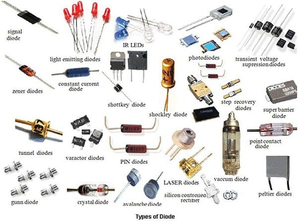
Diode is made up of two layers of semiconductor type P and N, formed from a combination of Silicon, Phosphorus and Boron. When these two layers come into contact with each other, they form two poles: Anode (A) on the P semiconductor side and Cathode (K) on the N semiconductor side. The characteristic of a diode is the ability to only allow current to flow from Anode to Cathode, helping to control the current in the circuit and prevent current from flowing in the opposite direction.
Common types of diodes on the market
Each type of diode has its own characteristics and applications in the circuit. Here are some common types:
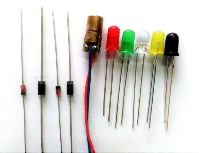
Rectifier diode: Specialized in converting alternating current to direct current. This type operates at low frequencies and can withstand large currents, commonly found in power supplies.
Light-emitting diode (LED): Widely used in lighting, signal lights and billboards thanks to its ability to emit light when an electric current passes through it.
Bidirectional pulse-limiting diode (TVS): Operates at high frequencies, from tens of kHz to MHz. Often used in switching power supplies and high-frequency electronic devices to protect circuits from sudden voltage spikes.
Varicap diode: This type of diode has the ability to change its capacitance according to the applied voltage level, often used in frequency regulation circuits such as radio receivers.
Zener diode: Operates in reverse bias mode, helping to stabilize the voltage in the circuit by maintaining a fixed voltage level when breakdown occurs.
Check diode with multimeter
To determine whether the diode is still working or not, you can use a multimeter and follow these steps:
Determine the polarity of the diode: It is necessary to correctly identify the positive pole (Anode) and negative pole (Cathode) before measuring.
Connect the measuring probe: Place the red probe of the meter on the positive pole, the black probe on the negative pole.
Check the measured value: If the display shows a voltage of 0.6 - 0.7V, the diode is still working well. For germanium diodes, this value will be lower, about 0.25 - 0.3V.
Reverse the probes: Place the red probe on the negative pole and the black probe on the positive pole. The diode will then be reverse biased and will not conduct electricity.
Evaluate the results: If the display shows [OL], the diode is still good. On the contrary, if there is a voltage value or nothing is displayed, the diode may be damaged due to an open circuit or a short circuit.
Tips for testing diodes with Fluke 87V Max
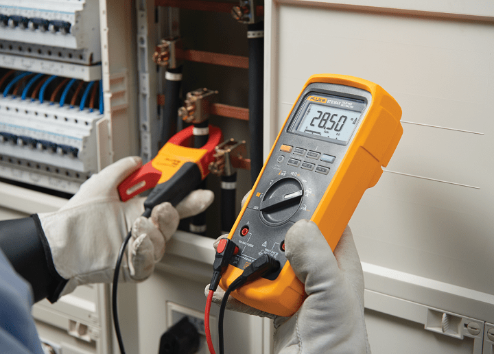
Fluke 87V Max is one of the high-end multimeters from FLUKE, high durability and accurate measurement, needless to say, suitable for testing diodes in many different working environments. Below are detailed instructions on how to use Fluke 87V Max to test diodes:
- Switch to diode measurement mode: Turn on the meter and turn the knob to "Diode Test" mode (triangle symbol with a dash).
- Connect the test probe:
Plug the black test probe into the COM port.
Plug the red test probe into the VΩ port.
- Measure in the forward direction:
Place the red probe on the positive terminal (Anode) and the black probe on the negative terminal (Cathode) of the diode.
If the diode is still working, the display will show a voltage drop, usually between 0.6 - 0.7V for silicon diodes, or 0.25 - 0.3V for germanium diodes.
- Measure in reverse:
Change the probe position: red probe on Cathode, black probe on Anode.
At this time, the diode will not conduct electricity, and the display will show OL (Over Limit), indicating that no current is flowing through.
- Evaluate the results:
If the measurement results are as above, the diode is still working normally.
If the voltage displayed in both cases or always OL, the diode may have an open circuit or a short circuit.
Frequently Asked Questions (FAQ)
Is a digital multimeter more accurate than an analog multimeter for testing a diode?
Yes. A digital multimeter displays the diode's forward voltage drop directly, making the test results easier to interpret while reducing errors caused by manual reading and user interpretation. In contrast, an analog multimeter primarily relies on the resistance scale and needle deflection to assess the condition of the diode. As a result, the accuracy of the measurement depends more heavily on the user's experience and interpretation.
Is it necessary to remove a diode from the circuit before testing it with a multimeter ?
No. However, for the most accurate measurement, it is recommended to disconnect at least one lead of the diode from the printed circuit board (PCB). This helps eliminate the influence of other components connected in parallel and ensures a more reliable test result.
Can an analog multimeter be used to test a diode?
Yes. An analog multimeter can test a diode using the resistance measurement range. When the diode is forward-biased, the needle should deflect. When the test leads are reversed, the needle should show little or no movement if the diode is in good condition. However, unlike a digital multimeter, an analog meter cannot display the diode's forward voltage drop.
What is the forward voltage drop of a good diode ?
For a silicon diode, the typical forward voltage drop is 0.55–0.75 V. For a germanium diode, the typical forward voltage drop is 0.2–0.3 V.
Why does the multimeter display "OL" when testing a diode ?
OL (Over Limit/Open Loop) indicates that the multimeter cannot detect current flowing through the diode. If OL appears during the reverse-bias measurement, the diode is functioning normally because it is blocking current. If OL is displayed in both the forward and reverse directions, the diode is likely open-circuited (failed open).
Can I use the resistance mode to test a diode ?
Yes, if your multimeter does not include a dedicated Diode Test function. However, the Diode Test mode provides more accurate results because it applies a controlled test current and directly measures the forward voltage across the PN junction.
Why does a diode sometimes test good and sometimes bad ?
Common causes include:
The diode is tested while it is still installed in the circuit.
Poor contact between the test probes and the diode leads.
A weak multimeter battery.
The diode has a temperature-dependent fault or only fails under load conditions.
Diode Fault Identification Table
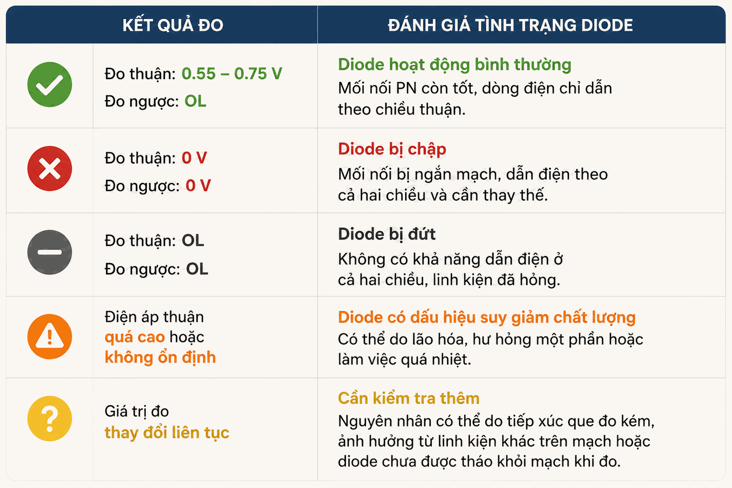
When should a diode be replaced ?
A diode should be replaced if any of the following conditions are observed:
The multimeter indicates that the diode is short-circuited or open-circuited.
The equipment frequently overheats during operation.
The power supply fails to rectify the output voltage correctly.
The protection circuit no longer functions properly.
An LED does not illuminate even though the power supply is normal.
A Zener diode can no longer maintain a stable reference voltage.
When replacing a diode, choose a replacement with equivalent electrical specifications, including the Maximum Repetitive Reverse Voltage (VRRM), Forward Current Rating (IF), and switching speed, to ensure proper operation and compatibility with the original component.