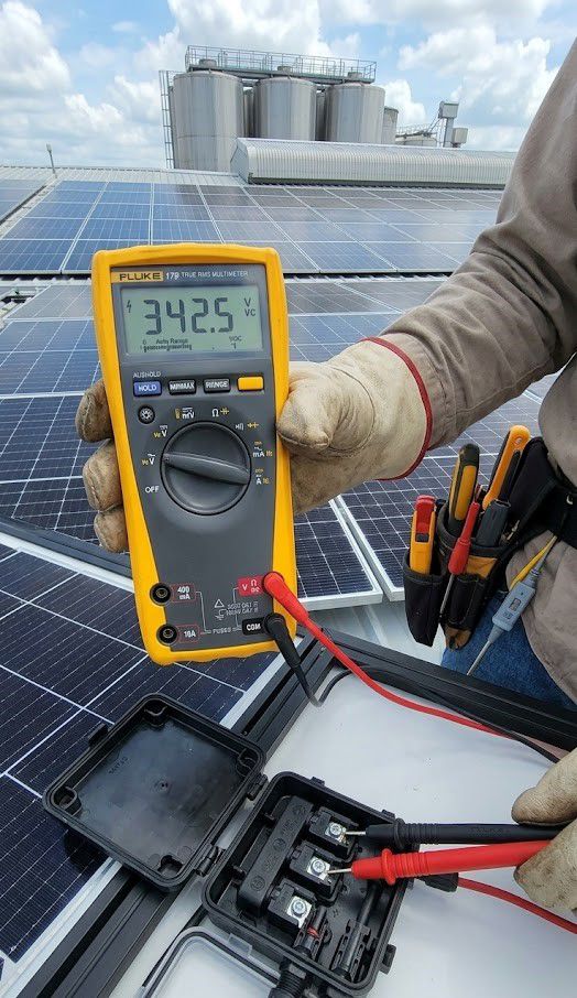
Before isolating macro-level system faults across an industrial plant, field engineers must always start by performing quick tests of open-circuit voltage (Voc) and short-circuit current (Isc) on individual panels using a multimeter to rule out isolated hardware failures. However, if these parameter readings match specifications while overall array output drops abnormally, identifying the root cause requires a broader system perspective.
Most cases of sudden voltage drop and power loss fall into four categories: shading/dirt accumulation, factory load fluctuations, degraded wiring and connections, or inverter glitches—each leaving distinct diagnostic signs recognizable before opening the electrical cabinet.
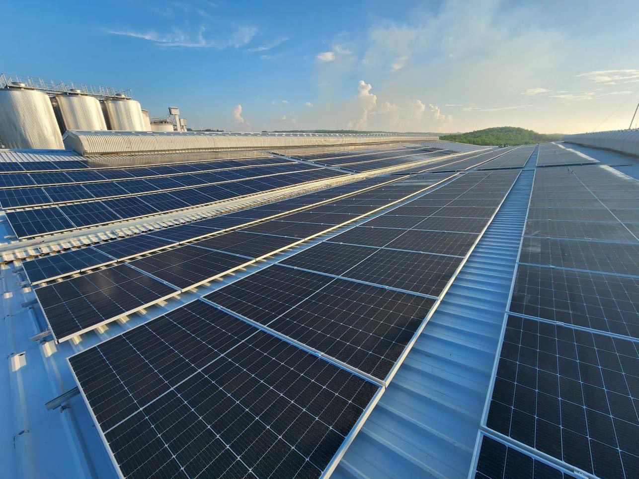
4 Signs to Isolate Causes Before Opening Electrical Cabinets
+ Voltage drops precisely around midday under full sun without equipment starting up suggests new shading or heavy dirt accumulation on panels.
+ Voltage drops coinciding with air compressor or welding machine startups and recovering after a few seconds points to factory load issues, not the solar system.
+ Gradual, persistent voltage drop increasing over time regardless of sunlight hours or load points to degraded wiring or loose connections.
+ Inverter screen displaying error codes or active warning LEDs immediately confirms an inverter issue, eliminating the need to check other categories.
1. Shading and Dirt: The Only Cause Resolved Immediately Upon Cleaning
Fallen leaves, newly erected nearby structures, or thick layers of accumulated dust and bird droppings can partially shade solar panels, causing current drops almost instantly. A shaded area on a single cell restricts string current, as the entire series output is limited by the weakest panel in line. This category is the most straightforward to resolve, with system output usually recovering fully right after cleaning or obstacle removal without leaving long-term damage.
2. Factory Load Fluctuations: Distinguishing Grid Issues from Solar System Faults
High-power machinery such as air compressors, welding units, and large motors draw inrush currents several times higher than rated levels upon startup, causing temporary internal grid voltage sags. To confirm whether the issue stems from load fluctuations rather than the solar array, measure the voltage at the solar-to-grid interconnection point right as large equipment starts; a simultaneous grid voltage drop confirms the root cause lies on the consumption load side, while the PV system is simply reacting to internal grid variations.
3. Degraded Wiring and Connections: The Most Frequently Overlooked Hazard
Undersized wire gauges relative to load current, excessively long cable runs, or loose connection points generate heat over time, leading to voltage drops across transmission lines. This type of drop occurs quietly without the sudden shifts seen in shading or load fluctuations, typically manifesting when loads peak or loose joints arc severely. Thermal imaging cameras provide the fastest method for detecting abnormal hot spots across connection points and breaker panels in a single scan without manual teardowns.
To verify whether the fault lies within load operations rather than the PV array, engineers can use high-performance multimeters like the Fluke 179 or Fluke 87V to measure voltage at the solar grid connection point right when heavy equipment starts up.
4. Inverter Derating vs. Hardware Failure: Read Fault Codes Before Disassembly
Inverters automatically throttle power output—a process known as derating—when ambient or internal cabinet temperatures exceed safe operating limits; this is a protective mechanism rather than a hardware failure. Actual hardware faults or prolonged overheating trigger explicit error codes and warning lights on the display. Reading the error codes first avoids unnecessary equipment teardowns while status remains unconfirmed.
Targeted Remedies by Root Cause to Prevent Unnecessary System Overhauls
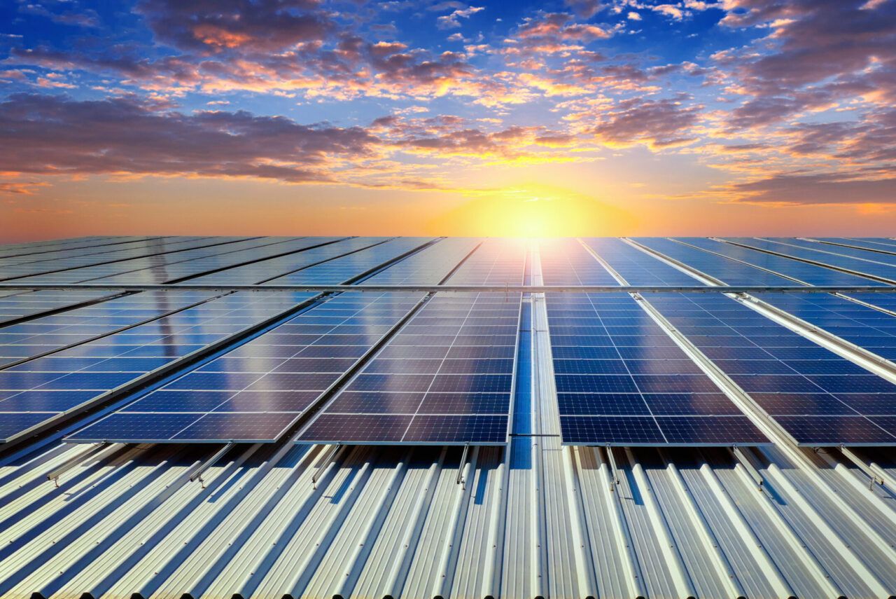
+ Shading and Dirt Accumulation: Clean solar panel surfaces periodically, trim surrounding trees, and clear new obstructions around the installation site.
+ Factory Load Fluctuations: Evaluate loads running in parallel, and consider installing voltage stabilizers or harmonic filters in areas with heavy machinery.
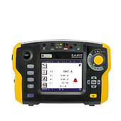
+ Wiring and Connection Issues: Measure insulation resistance, retighten all connection terminals, and increase cable cross-sections for long runs or heavy loads. For wiring and connection inspections, engineers should utilize insulation resistance testers (such as the Fluke 1507 series or specialized solar testers like the Fluke SMFT-1000) to test insulation resistance and secure all wiring terminals...
+ Inverter Issues: Inspect cooling fans, ensure proper cabinet ventilation, and avoid mounting inverters in unventilated areas or under direct sunlight exposure.
Mastering these four diagnostic indicators allows industrial facilities to shorten troubleshooting times and avoid dismantling entire systems due to temporary panel shading. The M&E and Solar Infrastructure Maintenance Seminar organized by EMIN in collaboration with Fluke in Da Nang on October 27, 2026, and in Southern Vietnam on October 30, 2026, will explore these diagnostic procedures alongside technical experts, featuring hands-on testing with field equipment. Register early to secure your spot and receive a full set of international-standard technical documentation!