Definition and Function of Clamp Meters
In the context of increasing emphasis on automation and energy optimization, clamp meters have become an important analytical tool, helping engineers gain a deeper understanding of the operating status of electrical circuits to predict maintenance for continuous system operation without interruption or direct intervention.
Definition of Clamp Meters
Clamp meter is a specialized measuring device used to measure current with a wide measurement range from 100mA to 2000A. The name of this measuring instrument is derived from the unit of current intensity, ampere.
Functions of Clamp Meters
The main function of a clamp meter is to measure current with a wide measurement range. In fact, clamp meters are gradually taking on the role of a multi-parameter measurement platform: measuring voltage, resistance, and digital signal processing. Clamp meters are not just energy measuring devices; they also help people understand the state of electrical circuits, predict maintenance, and proactively control electrical systems. Safety, flexibility, and analytical capabilities are paramount.
However, what is even more noteworthy is their ability to extract real-time data. In real-world operating environments, current is rarely absolutely stable. Phenomena such as inrush current, load oscillations, or waveform distortion all contain crucial information about equipment status. True RMS clamp meters can calculate the true RMS value of nonlinear signals, resulting in more accurate measurements compared to traditional averaging methods. When combined with functions for recording peak and minimum values or filtering high-frequency noise, clamp meters not only "read" current but also help interpret system behavior. Clamp meters are no longer just for quick checks; they are becoming part of predictive maintenance processes, detecting early abnormalities such as overload, attenuation, or phase imbalance – factors that can lead to failure if not addressed promptly.
A frequently overlooked technical aspect is the influence of measurement conditions on accuracy. The position of the conductors in the clamp jaws, the presence of multiple parallel conductors, or electromagnetic interference from the surrounding environment can all skew the results. This requires users to not only understand the device but also grasp the physical nature of the measurement. Therefore, clamp meters – despite their ease of use – remain a highly technical tool.
Operating Principle of Clamp Meters
Essentially, clamp meters are devices that measure current based on the principle of electromagnetic induction.
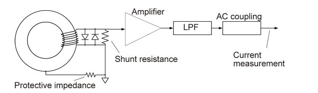
- The current transformer (CT) principle: is used in traditional devices to measure alternating current with a wide measurement range and high accuracy. When current flows through a conductor, the magnetic field generated around the wire is detected by the clamping jaws – acting as a magnetic core. This magnetic field signal is then converted into an electrical signal and processed to display the current value. The core difference lies in the fact that the measurement process does not require interrupting the circuit or direct contact, thereby minimizing the risk of electrical arcing and connection errors. The limitation is that it cannot measure direct current.
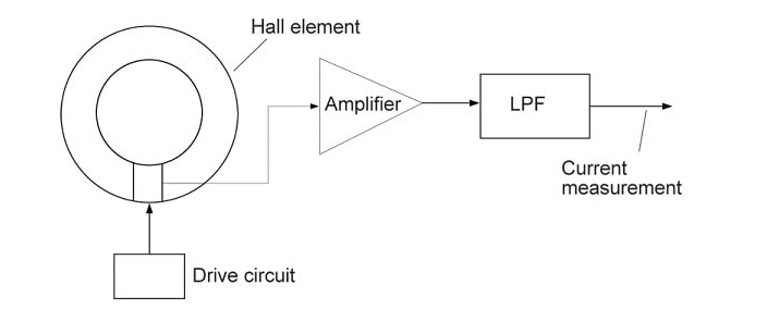
- Hall principle: When current flows through a conductor, it creates a magnetic field around it. The Hall element in the magnetic core senses this magnetic field and converts it into a voltage. This voltage is then converted back into current, thereby measuring the current value in the circuit. With the development of Hall sensor technology, modern AC/DC clamp meters are capable of measuring both direct current and direct current – something previously almost impossible with conventional magnetic clamp structures. This is a particularly important factor in the context of power systems increasingly expanding into the renewable energy sector, where DC current plays a dominant role. The drawback may be lower accuracy due to the influence of external factors such as the sensor housing, magnetic circuit, and magnetic core design.
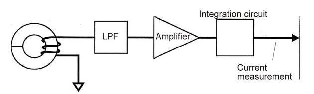
- Rogowski principle: Differentiates the output voltage waveforms at the ends of the coil, then integrates these waveforms to calculate the current value. The coreless coil reduces the size and increases the flexibility of the clamp meter.
See some popular clamp meter models: Hioki clamp meters, Fluke clamp meters, Kyoritsu clamp meters, Uni-T clamp meters