Fiber optic loss and its main causes?
What is fiber optic loss?
Fiber optic attenuation is the loss of light signals when transmitted through fiber optic cables, causing the signal to weaken and reduce the quality of data transmission. Correcting attenuation is an important step to ensure the network system operates stably and effectively.
Causes of deterioration
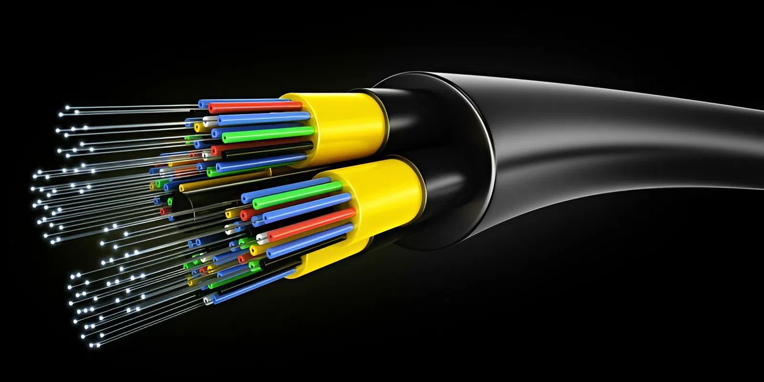
Fiber loss can come from many factors such as fiber inhomogeneity, breaks, misaligned splices or excessive bends. Identifying the correct cause helps to choose the appropriate treatment plan, minimizing signal loss.
Steps to effectively overcome fiber optic attenuation
Step 1: Check and evaluate the loss with specialized equipment
First, you need to use an optical loss meter to accurately determine the loss level as well as the location of the loss. EXFO iOLM software allows multi-wavelength measurement, fast and accurate analysis to help you understand the condition of the optical fiber.
Step 2: Determine the cause of the loss
Based on the measurement results, analyze whether the loss is due to poor connections, dirty connectors, severe breaks or bends. Understanding this cause will help the next troubleshooting step achieve optimal efficiency.
Step 3: Clean and Repair the Connector
Most attenuation problems come from dirty or poor quality connectors. Using a specialized cleaning tool to clean the connector will significantly reduce attenuation. If the connector is severely damaged, you should replace or rework the connector to ensure good contact.
Step 4: Repair or replace the faulty cable
If you find a break or bend that causes signal loss, you need to replace the damaged fiber or reconnect the fiber according to technical standards. When operated correctly, the fiber loss will be completely eliminated. Thanks to the EXFO MPO LXM-MM device, you can accurately count the location of the break or splice failure within seconds without having to disassemble the entire fiber.
Step 5: Recheck and confirm the results
After fixing, re-measure with an attenuator to ensure the attenuation level is up to standard. This is a step that cannot be skipped to ensure that the above operations have improved the transmission quality.
You can see that fixing fiber optic attenuation is not complicated if you know how to use the right tools and follow the right process.
In addition, you can refer to the following article to better understand the optical attenuation results:
Why are the optical attenuation measurement results in the lab and in the field often different?
Advice
Among the many types of fiber optic loss meters available such as EXFO FOT-302x or can be viewed in the Optical Attenuation Meter category, it is necessary to consider the characteristics of each device and the actual usage requirements to achieve optimal testing and troubleshooting efficiency.
Solutions such as EXFO's iOLM allow automatic analysis of the entire optical link, shortening the operation time and reducing errors during the measurement process, making the loss processing process faster and more stable.
Conclude
Correcting optical fiber loss is a necessary step to maintain the stability of the optical network and prolong the life of the system. The article has presented the basic steps to make the process clearer and more practical.
Equipping the right measuring equipment and following the correct procedure will help the inspection and maintenance work achieve accurate results. Readers can refer to the specialized optical loss measuring machines that are commonly used in the industry to choose the equipment that meets their needs.