This is why most fire protection acceptance dossiers require verification of coating thickness after application. However, many people still confuse wet film thickness with dry film thickness, or use incorrect measurement methods, resulting in data that fails to meet requirements.
The following article summarizes common standards, practical measurement procedures, and tips for selecting the appropriate equipment to inspect fire-retardant coatings on steel structures.
Latest Dry Film Thickness (DFT) Standard Table for Steel Structures
There is no single, fixed figure applicable to every project. The thickness of the fire-resistant coating depends on various factors, such as the type of coating, the shape of the steel structure, the section factor (Hp/A), service conditions, and the design fire-resistance rating.
Final specifications must always adhere to the manufacturer's calculation tables, which have been validated through testing against standards such as BS 476, EN 13381, or ASTM E119.
Thickness specifications based on fire resistance duration (45 to 120 minutes)
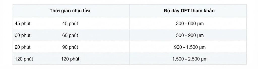
The values above are for guidance only. During acceptance, the engineer must cross-reference them directly with the DFT chart provided by the paint manufacturer for each specific type of beam, column, or steel structure.
Wet Film Thickness (WFT) and Dry Film Thickness (DFT): which figure is used for acceptance?
Many application crews check the Wet Film Thickness (WFT) immediately after spraying and consider it sufficient. In reality, WFT merely helps monitor the amount of paint applied, allowing the operator to adjust the spray equipment or application speed.
Once the solvent evaporates and the coating fully cures, the thickness decreases to form the Dry Film Thickness (DFT).
The figure used in project acceptance, inspection, and handover documentation is always the DFT.

Relying solely on WFT measurements carries a high risk of the final thickness falling below specifications due to solvent evaporation during the curing process.
The golden rule for checking the thickness of fire-resistant coating in accordance with international standards
Selecting the correct measurement locations is just as important as using the correct equipment. Many projects require re-inspection simply because the chosen measurement points do not comply with the SSPC-PA 2 or ISO 19840 standards.
Instead of taking random measurements at a few easily accessible spots, the structural surface should be divided into representative areas. Multiple measurements should be taken within each area to calculate an average value before determining pass/fail status.
Common principles for coating acceptance include:
+ The average value must meet the specified design thickness.
+ There should be no individual readings below the limits permitted by the applicable standard.
+ Reports must fully document the measurement locations, times, and equipment details.
Devices capable of data logging, averaging, and report generation can accelerate the acceptance process while minimizing errors during documentation.
Method for grid layout and selection of measurement points on steel beam structures
Steel I-beams, H-beams, and box girders often feature multiple contact surfaces and hard-to-reach corners. Measuring only on large, flat surfaces fails to provide an accurate assessment of the coating across the entire structure.
Typically, engineers divide the structure into smaller zones and select multiple measurement points across the flanges, webs, and transition edges. This approach helps identify areas where the coating is insufficient due to spray gun accessibility issues.
Separate probes offer a distinct advantage in this scenario. Unlike integrated probes, separate probes can easily reach tight corners, narrow gaps, or the undersides of steel beams while maintaining measurement stability.
Why are standard gauges unsuitable for fire-retardant coatings?
Fire-retardant coatings are typically much thicker than standard industrial coatings; some types can reach a thickness of several thousand microns upon completion.
Many low-cost devices are suitable only for thin coatings or offer low resolution, making them prone to errors when measuring thick paint layers.
In addition to the ability to measure on magnetic steel substrates, specialized equipment must meet requirements such as:
+ A sufficiently wide measurement range.
+ High resolution.
+ Calibration using standard foils.
+ Measurement data storage.
+ Multi-point averaging.
Possession of a valid calibration or inspection certificate.
A device with an expired calibration or of unknown origin is typically not accepted by supervision consultants or fire safety inspection authorities.
Tips for Contractors on Selecting an Accurate Coating Thickness Gauge
Contractors often prioritize measurement speed, whereas supervisors prioritize data storage and retrieval capabilities. Therefore, equipment selection should be based on specific operational needs rather than just the purchase price.
Key criteria to consider include:
- Detachable probes for flexible measurement on steel beams.
- Large memory capacity to store all project data.
- Rapid calibration using standard foils.
- Support for measurements on both steel and aluminum for multi-material projects.
- Availability of calibration certificates for project acceptance documentation.
Top 3 Specialized Coating Thickness Gauges for Fire Protection System Acceptance
For civil and industrial projects, many contractors opt for specialized coating thickness gauges capable of rapid, stable measurements that meet acceptance criteria.
Commonly used models include:
- Elcometer 456: features a separate probe and large data storage capacity; suitable for inspecting coatings on steel structures.
- DeFelsko PosiTector 6000: offers high accuracy, multiple probe options, and report generation capabilities.
When frequently measuring I-beams or hard-to-reach areas, it is advisable to prioritize versions with separate probes to facilitate easier handling and minimize the risk of measurement errors.
Fire-retardant coating thickness is not merely a technical specification; it directly determines the level of protection afforded to steel structures during a fire. Even minor discrepancies during application or inspection can necessitate rework of the entire scope of work prior to final acceptance.
Understanding the distinction between WFT (Wet Film Thickness) and DFT (Dry Film Thickness), adhering to standard sampling procedures, and using appropriate measuring equipment ensures that inspection data accurately reflects coating quality, thereby expediting the acceptance process and minimizing additional costs for the contractor.