What is the function of the information card?
Continuity is the state in which the current can flow through the circuit continuously. When the wire is broken or the connection is faulty, the transmission of electricity will be interrupted, directly affecting the operation of electrical and electronic devices.
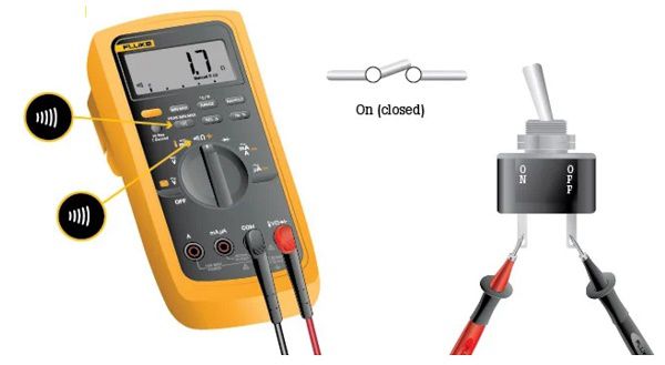
In this case, you can use a multimeter or clamp meter to check the conductivity and signal transmission. Measuring continuity helps determine whether the device has a fault due to a broken circuit, thereby providing a reasonable repair plan
Note that both a multimeter and a clamp meter can be used to measure continuity. If the multimeter does not have a separate continuity measurement function, you can still check by using the resistance measurement mode.
Alternatively, another simple way to test is to connect a normally functioning electrical device to an electrical outlet via the wire to be tested. However, for PCB circuits, where there are many complex electrical paths, the use of a multimeter is absolutely necessary to quickly and accurately identify discontinuities in the circuit.
So when do we need to measure continuity?
Continuity testing is used in many situations to determine if there is a break in a circuit. Here are some common situations where you might need to perform a continuity test:
Check the solder joint: Make sure the solder joint has good contact and is conductive. If you don't have experience with visual inspection, you can use a multimeter to quickly determine if the solder joint is faulty.
Check the wires and cables: Wires, power cables, charging cables, or headphone cables can be broken internally without being visible from the outside. Measuring continuity helps determine whether the wire is intact or broken.
Check for solder joints: When soldering components, if you are inexperienced, you may accidentally cause two solder joints to touch each other, causing a circuit blockage.
Check circuit design and verify connections: To ensure that the circuit is designed correctly according to the schematic, checking for continuity is a necessary step. In addition, this method is also used to test fuses, automotive electrical systems, lamp holders, bulbs, plugs, and other wire connections.
Notes when measuring circuit continuity
To ensure accurate continuity measurement and avoid damage to the device, you need to note the following important points:
Do not supply power to the circuit when measuring: When testing for continuity, the circuit or connecting wire must be completely disconnected from the power source. The multimeter uses resistance measurement mode to test the conductivity, automatically supplying a small voltage level for measurement. If the circuit is still energized, the measurement result may be inaccurate or damage the measuring device.
Check the operation of the multimeter before measuring: To ensure that the meter is working properly, switch the meter to continuity mode, then short the two test leads together. If the meter makes a "beep" sound, it means that the continuity function is still working properly and you can use it with confidence.
Choose simple measurements and note when measuring continuity
When testing for continuity with a multimeter, it is a non-directional measurement. This means that you can swap the probes around and the result will remain the same, unaffected.
In some cases, if you are testing for continuity between two points where a capacitor is connected, you may hear a short beep. This happens because the voltage the multimeter is testing is used to charge the capacitor, causing the meter to indicate continuity for a moment.
Currently, there are many popular quality multimeters on the market such as Kyoritsu 1018H, Proskit MT-1233D, Kyoritsu 1009... You can refer to other product lines that suit your needs to ensure accuracy and convenience when measuring.