In many cases, the issue is addressed by increasing welding time or productivity, yet results fail to improve because the root cause actually lies in the welded product, the materials, or the design.
What is a non-hermetic ultrasonic weld?
An imperfect weld occurs when two surfaces fail to bond completely after the welding process. While the product may appear joined upon visual inspection, testing for airtightness or tensile strength reveals that the weld separates easily, resulting in gaps or leaks.
The root cause is typically insufficient ultrasonic energy or improper energy transmission, causing the material to soften only locally rather than melting uniformly across the entire contact area.
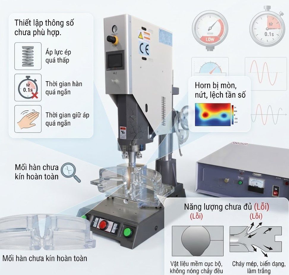
Parameters are not set appropriately
Welding parameters determine the amount of energy transferred to the workpiece. Even a single unsuitable value can result in a weld that lacks a proper seal.
Key parameters to review include:
- Insufficient clamping pressure, preventing tight contact between the parts.
- Excessively short welding time, preventing the material from melting completely.
- Insufficient hold time after welding, causing the mold to separate before the material has stabilized.
- Vibration amplitude that is too low, resulting in inadequate energy transfer to the weld zone.
In practice, increasing power does not always solve the problem. Excessive energy can lead to edge burning, deformation, or whitening of the weld area.
Worn welding horn or mold
The horn is the component that directly transmits ultrasonic vibrations to the product. After prolonged use, the horn's surface may wear down or crack, or its resonant frequency may shift.
Consequently, energy is no longer distributed evenly across the entire welding area. While some spots receive sufficient energy, others fail to melt adequately, resulting in tiny gaps that are difficult to detect with the naked eye.
If this condition persists, the defect rate will gradually increase, even though all machine parameters remain unchanged.
The material surface is not yet clean
This is a frequently overlooked cause.
Even a thin layer of oil, plastic dust, moisture, or oxidation is enough to create a minute gap between the two contact surfaces. Ultrasonic vibrations passing through this zone are attenuated, resulting in uneven material melting and significantly reduced bonding strength.
For products requiring a high degree of seal integrity such as plastic containers, electronic components, or medical devices the pre-welding cleaning process is subject to strict controls.
The material or product design is not yet suitable
Not all materials yield the same welding results.
Some common scenarios include:
- Two parts made of different types of plastic.
- Variations in additive ratios between material batches.
- Suboptimal weld joint design.
- Guide grooves or Energy Directors that are too small or too large.
- Even when the machine is operating normally, an unsuitable product design can prevent the molten plastic from concentrating at the specific location requiring the bond.
The frequency and vibration system are not operating stably
An ultrasonic welding machine operates effectively when the converter, booster, and horn resonate at the designed frequency.
If the system experiences resonance deviation, the energy transmitted to the product decreases significantly. This phenomenon is often accompanied by signs such as:
Uneven welds.
Inconsistent sealing (some areas sealed, others open).
Inconsistent product quality.
Higher-than-normal energy consumption.
This is also why many factories periodically inspect the horn and vibration system rather than relying solely on monitoring parameters via the control screen.
How can incomplete ultrasonic welds be minimized?
To reduce the defect rate, engineers typically conduct checks in a sequence ranging from simple to complex, rather than adjusting parameters randomly.
The process generally begins with:
- Visually inspecting the welding horn and mold.
- Checking the cleanliness of the material surfaces.
- Verifying the material types of the two components.
- Adjusting welding pressure, weld time, hold time, and vibration amplitude.
- Re-evaluating the weld zone design if the defect persists.
This approach helps accurately identify the root cause while avoiding the introduction of new defects when altering machine parameters.
Conclude
When the defect rate rises unexpectedly, in addition to inspecting the horn and materials, many factories also review the equipment's parameter adjustment capabilities. Danrel ultrasonic welding machines allow for the precise configuration of welding time, hold time, welding pressure, and vibration amplitude; this enables engineers to easily optimize the process for specific product types, rather than simply increasing power output manually.