System overview
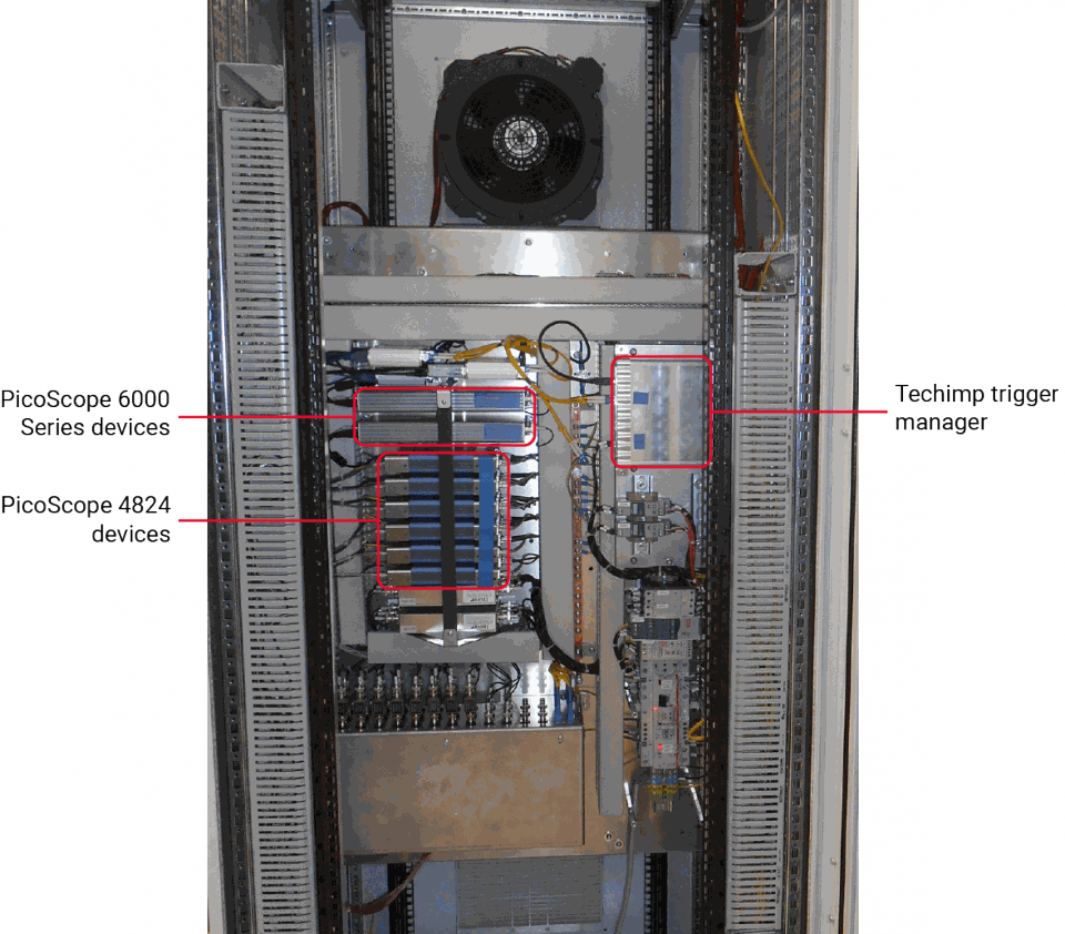
The behavior of transients in high-voltage cables is a matter of concern, especially when overhead lines alternate with cable links. That’s why TenneT ordered Techimp’s PCMONS for their Randstad 380 kV Noordring Project. The PCMONS is a continuous permanent monitoring system capable of acquiring transients based on amplitude thresholds. The PCMONS acquires all parameters simultaneously each time a transient occurs, with a time stamp accuracy of 100 ns to allow correlation with events acquired from other systems.
The purpose of the system is to collect evidence of the behavior of a combined transmission cable/overhead line and confirmation of the mathematical model in a transient regime, and to obtain a possible indicator of the degradation of the system (residual lifetime) as a result of transients occurring in time.
The PCMONS is installed over a 40 km high-voltage power network in the north of the Netherlands, distributed in eight units covering 13 locations and four substations. It is composed of sensors connected to cabinets hosting amplifiers, acquisition instruments from Pico Technology and the triggering logic. The cabinets are connected via fiber optic to one server for each unit, where the triggering signals are distributed and the data is collected and transmitted to the central unit. This is the central server where data is stored for visualization and analysis using the proprietary human/machine interface (HMI) software, Techimp TiSCADA.
The PCMONS is responsible for acquiring, processing, archiving and presenting information concerning the power connection, and all functions defined are accessible to the user. The system is able to acquire continuous and impulsive voltages and currents, and raw partial discharge (PD) waveforms that are stored in the local servers.
All inputs have an adjustable trigger level above which the recording is started. An event detected on one of the sensors triggers all other measurements inside the same unit. In particular, each input has a dedicated trigger, each trigger level is adjustable between zero and the maximum input level and trigger levels are adjustable from the HMI and remotely.
The PCMONS records 1 s of data after the trigger for all inputs with frequencies below 1 MHz, or 20 ms of data for frequencies above 1 MHz.
Description of parameters to be monitored
Each of the following parameters is measured thanks to the performance of PicoScope oscilloscopes, leveraging either the ability of the PicoScope 6000 Series to sample three channels at 500 MHz or the ability of the PicoScope 4824 oscilloscope to sample at 1 MHz on seven channels plus trigger. PicoScope represents a perfect solution, combining compact dimensions, accuracy and bandwidth with user friendliness.
These instruments were installed on a similar system in 2013 and demonstrated no drift, granting perfect repeatability of the measurement.
Phase voltage transients (0 to 693 kV, DC to 1 MHz; PicoScope 4824)
Voltage measurement using the high-voltage resistive-capacitive (RC) divider in a substation.
Acquisition with a high sample rate, occurring only when the system is triggered.
Phase voltage oscillations (0 to 693 kV, DC to 10 kHz; PicoScope 4824)
Hardware/software summation in order to provide the voltage on a particular line.
Acquisition with a low sample rate, occurring continuously. Output in the form of an RMS voltage value over a period of time.
Current measurements in each phase (0 to 4 kA, 0.2 Hz to 2 kHz; PicoScope 4824)
Current measurement using the high-voltage current transformers (HVCTs) in a substation.
Acquisition with a high sample rate, occurring only when the system is triggered.
Overhead line current oscillations, (0 to 4 kA 0.2 Hz to 2 kHz; PicoScope 4824)
Hardware/software summation of the various incoming and outgoing currents in a bus bar in order to provide the current through a particular line.
Acquisition with a low sample rate, occurring continuously.
Current in each cable (0 to 22 kA, 0.2 Hz to 1 MHz; PicoScope 4824)
Current measurement using Rogowski coils mounted at the terminations of each cable.
Acquisition with a high sample rate, occurring only when the system is triggered.
Cable screen current (0 to 22 kA, 0.2 Hz to 1 MHz; PicoScope 4824)
Cable screen current passes through the outer sheath of each cable, measured using Rogowski coils installed on the grounding of the cable sheaths.
Acquisition with a high sample rate, occurring only when the system is triggered.
Current oscillations in each cable (0 to 2 kA, 0.2 Hz to 2 kHz; PicoScope 4824)
Current measurement with a low sample rate.
Acquisition occurs continuously. Output in the form of an RMS current value over a period of time.
Partial discharges in the terminations (0 to 1000 pC, 500 MHz; PicoScope 6000 Series)
Measurement of partial discharge in the terminations at the connection between the overhead line and the underground cable, using the embedded sensors inside the terminations.
Surge arrester current (120 kA, 1 Hz to 5 Hz; PicoScope 4824)
Surge arrester current through the ground point of each surge arrester, measured using Rogowski coils installed on the groundings of the surge arresters.
Acquisition with a high sample rate, occurring only when the system is triggered.
Surge arrester leakage current (12 mA, 0.1 to 650 Hz; PicoScope 4824)
Surge arrester leakage current through the ground point of each surge arrester, measured using Rogowski coils installed on the groundings of the surge arresters.
Acquisition with a high sample rate, occurring only when the system is triggered.
Voltage at each joint earth screen (DC to 10 kV DC to 1 MHz; PicoScope 4824)
Voltage measurement using the voltage divider installed in each link box (i.e. the box connecting the high-voltage cable screens).
Acquisition with a high sample rate, occurring only when the system is triggered.
Current through each joint earth screen (0 to 22 kA, 0.2 Hz to 1 MHz; PicoScope 4824)
Current measurement using Rogowski coils mounted on each intersection of the high-voltage cable screens.
Acquisition with a high sample rate, occurring only when the system is triggered.
Partial discharges in the joints (0 to 1000 pC, 500 MHz; PicoScope 6000 Series)
Measurement of partial discharge in the cable joints using the embedded sensors inside the joints at the joint bays.
Visualization
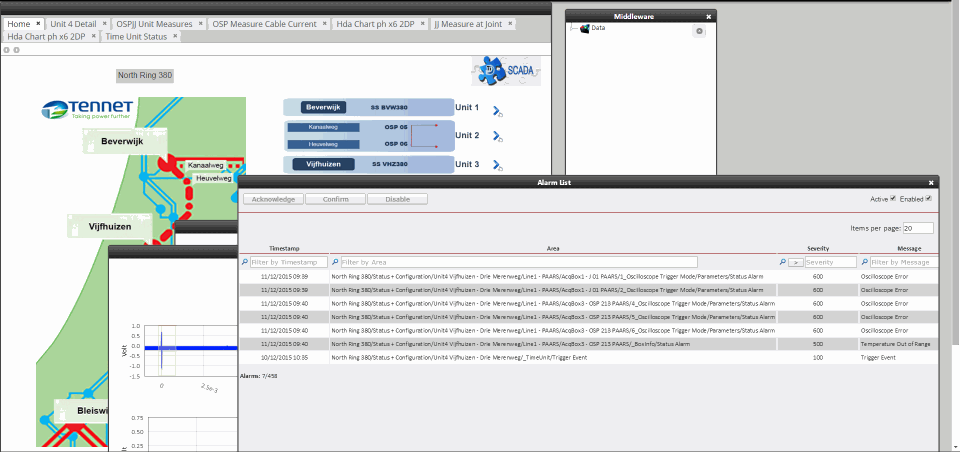
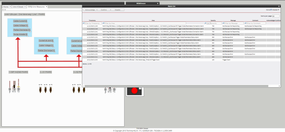
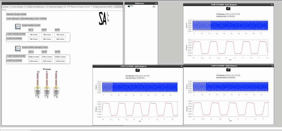
The HMI, based around Techimp’s proprietary TiSCADA software, gives to the customer the chance to access the full system, visualizing the waveforms and listing the events, location by location.
Waveforms
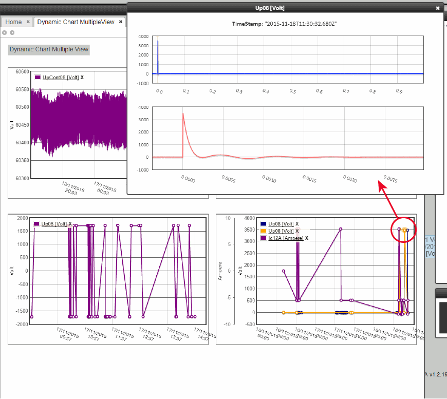
Waveforms are organized as a collection of events in time. Each acquisition event is defined by the time of its occurrence and a scalar value that characterizes the waveform, so the visual representation of this collection is a trend graph.
Events
Events are displayed by choosing the unit from a schematic map, and then the location from a diagram.